Providing Eligibility Criteria On Turbocharger Filter Silencer Design Processes
Supply of ventilation air to either the engine room or diesel engine directly affects engine performances.
Main criteria is supply of air volume and pressure into the cylinder. When Air starts to come until the cylinders, there many points which behave as restrictions. These are ventilation grills. ventilation fans, ventilation casings, misteliminators, manual or pneumatically adjusted fan dampers, number of bending of ventilation casing, cleanness of casings, air flow speed, air filters, turbocharger filter and silencers, engine’s scavenge air cooler restrictions.
Here, we focused on optimum required air need through turbocharger for local diesel engine. While researching actual need, new turbocharger filter were designed and manufactured for engine manufacturer.
1. Introduction.
Diesel engine performances may vary from many different variations which affect and change both efficiency and emissions results. One of the main issues are supplied ambient air pressure and turbocharger related restrictions. In this topic, New design turbocharger filter with silencer factory test results for local manufactured TULOMSAŞ brand TLM 16PA4-185 type diesel engines which is manufactured under Semt Pielstick license, and expected results were considered for new building ferries which will be used at Lake Van.
Two-stroke or four-stroke diesel engines have high efficient turbochargers in order to get more power. Today’s technology brings diesel engine manufacturers to obtain highest productivity from fossil based fuels. Thus, competitive engines take bigger piece on market worldwide. Market trends and new research and developments improve low fuel consumptions per kW/Hp produced so It let us to release lowest emission rates.
There are also other factors which affect total efficiency on ships. Long term researches and operational experiences created a new approach to shipping industry. Energy Efficiency Design Index (EEDI) is just one of the last decade of future mandatory requirement of International Maritime Organization (IMO).
NOx and PM are the emission components of most concern from diesel engines. Although the air/fuel ratio in a diesel cylinder is very lean, the air and fuel are nota homogeneous charge as in a gasoline engine. As the fuel is injected, the combustion takes place at the flame-front where the air/fuel ratio is near stoichiometry. At localized areas, or in cases where light ends have vaporized and burned, molecules of carbon remain when temperatures and pressures in the cylinder become too low to sustain combustion as the piston reaches bottom dead center.
Therefore, these heavy products of incomplete combustion are exhausted as PM. EPA believes that the new emission standards for marine diesel engines can be met using technology that has been developed for and used on locomotive, land based non-road, and highway engines. [EPA].
False design and products cause incomplete burning on diesel engine.Turbocharger selection and its filters are main compenents of air intake system of any brand diesel engine. Both components have great impact on efficient combustion results. Turbocharger maximum or optimum efficiency can be achieved by the very accurate coordination of turbocharger and diesel characteristics during design and engine test stages. Engine manufacturers are named their Maximum Continous Ratings as MCR. Duration of MCR at peak loads may vary from one to another manufacturer’s decision. Maximum allowable duration changes according to engine manfacturer but, these requirements finally decided by buyer’s recommendation such as light duty and heavy duty engines.
On the other hand, it is also well known that marine diesel engines are operated on lower loads than maximum design MCR loads. Based on practical experience, we can conclude that propulsion marine engines are generally operated between 75% -85% and auxiliary engines operated between 50% -75% of their MCR. These loads for auxiliary engines may even lower than stated values since there are random started and stoped consumers on board a vessel.
2. Material and methodology.
On application methodology, existing engine specifications and air requirements, turbocharger requirements and restrictions, barometric effects because of sea level altitude(elevation), engine room ISO 3046-1:2002(E) and ISO 15550:2002(E) reference requirements, International Association of Classification Societies (IACS) rule M28 and atmospheric conditions defined by CIMAC were main topics which should be considered and analyzed.
Engine Technical Fundamentals & Characteristics
- Cycle: 4 strokes, single acting
- Number of Cylinders: 16
- Arrangement: Vee-form at 90º
- Maximum Continuous Power Rating: 1770 kW (2400 metric HP)
- Cylinder Bore: 185 mm
- Piston Stroke: 210 mm
- Swept Volume (per Cylinder): 5.65 L
- Compression Ratio: 13.5/1
- Mean Piston Speed: 10.5 m/sec (at 1500 rpm)
Air and Gas Characteristics
- Number of Superchargers: 2 turbochargers
- Type of Supercharger: BBC VTR 250 or HS 400
- Weight of Intake Air (per Hour): 12,930 kg
- Maximum Pressure Loss at Turbocharger Air Inlet: 20 millibars
- Charge Air Pressure: 1.4 bar (1.43 kg/cm²)
- Weight of Exhaust Gas (per Hour): 13,340 kg
- Cylinder Head Exhaust Gas Outlet Temperature: 490ºC
- Turbine Inlet Exhaust Gas Temperature: 590 ºC
- Turbine Inlet Exhaust Outlet Temperature: 520 ºC
- Gas Pressure at Turbine Inlet: 0.87 bar (0.89 kg/cm²)
Reference Atmospheric Conditions (Defined by CIMAC)
- Ambient Temperature: 20 ºC (68 ºF)
- Atmospheric Pressure: 981 mb (29 inches of mercury)
- Relative Humidity: 0.6
- Water Temperature at Air-Cooler Inlet: 20 ºC (68 ºF)
International Association of Classification Societies (IACS) Rule M28
- Barometric Pressure: 1,000 mbar
- Air Temperature: 45 ºC
- Seawater Temperature: 32 ºC
- Relative Air Humidity: 60%
ISO 3046-1:2002(E) and ISO 15550:2002(E) ISO Ambient Reference Conditions/Requirements
- Barometric Pressure: 1,000 mbar
- Turbocharger Air Intake Temperature: 25 ºC
- Charge Air Coolant Temperature: 25 ºC
- Relative Air Humidity: 30%
Although Lake Van is situated at an altitude of 1,640 m (5,380 ft) with harsh winters, it does not freeze due to its high salinity except occasionally the shallow northern section. The lake water is strongly alkaline (pH 9.7 – 9.8) and rich in sodium carbonate and other salts, which are extracted by evaporation and used as detergents. Lake Van is situated in the highest and largest region of Turkey, which has a harsh continental climate. Average temperatures in July are between 22 and 25 °C, and in January between -3 °C to -12 °C. In particularly cold winter nights the temperature reaches -30 °C. Lake Van mitigates the climate somewhat, so in the city of Van, on the shore of the lake, the average temperature in July is 22.5 °C, and in January -3.5 °C. [Lake Van, Wikipedia].
Altitude of 1,640 m creates pressure change at this level. Pressure is generally increase with higher altitudes and increase quickly to sea level. If we climb upper hills, weight of air on our body is lowered. Pressure increases at lower levels rapidly. This is result of increase of different gases at lower levels. If we collect all gases in a closed column, total pressure of column will increase in conjunction with weigh of gases will increase.
Atmospheric Pressure and Altitude Factors
- Key Factor: Temperature’s impact on pressure variation with altitude
- Pressure at Sea Level:
- 1 Atmosphere = 1.01325 bar
- Equivalent to 1013.25 millibar (mb)
- 101326 Pascal
- 1013.25 hectopascal (hPa)
- 29.92 inches Hg
- 760 mm Hg
- 14.7 lb/inch²
Composition of the Atmosphere
- Reference: Table 3 (mentioned in your content)
- Details: Lists existing gases in the atmosphere along with their respective percentages
| Gas Name | Symbol/Chemical Formula | % Volume at Dry Air |
|---|---|---|
| Nitrogen | N2 | 78,08 |
| Oxygen | O2 | 20,95 |
| Water | H2O | 0 to 4% |
| Argon | Ar | 0,93 |
| Neon | Ne | 0.0018 |
| Helium | He | 0.0005 |
| Methane | CH4 | 0.00017 |
| Hydrogen | H2 | 0.00005 |
| Nitrous Oxide | N2O | 0.00003 |
| Ozone | O3 | 0.000004 |
Heating up of earth and air that close to ground level depend on sun radiation. That’s why; warm air is placed to ground level. Temperature variation with altitude change is identified as “lapse rate”. Lapse rate at troposphere is generally -6.5 °C/km. Lapse rate at dry air is -9.8 °C/km. As result, pressure will be dramatically different at 1,640 m.
Conceptional design was carried out and final prototype products were manufactured under these information and restrictions above. Turbocharger provider Huispano Suiza supplies to locomotive industry in common. Since there is no available place on engine for vertical installation of turbo silencer and filter. Requirement was forced us to pass beyond standard designs.
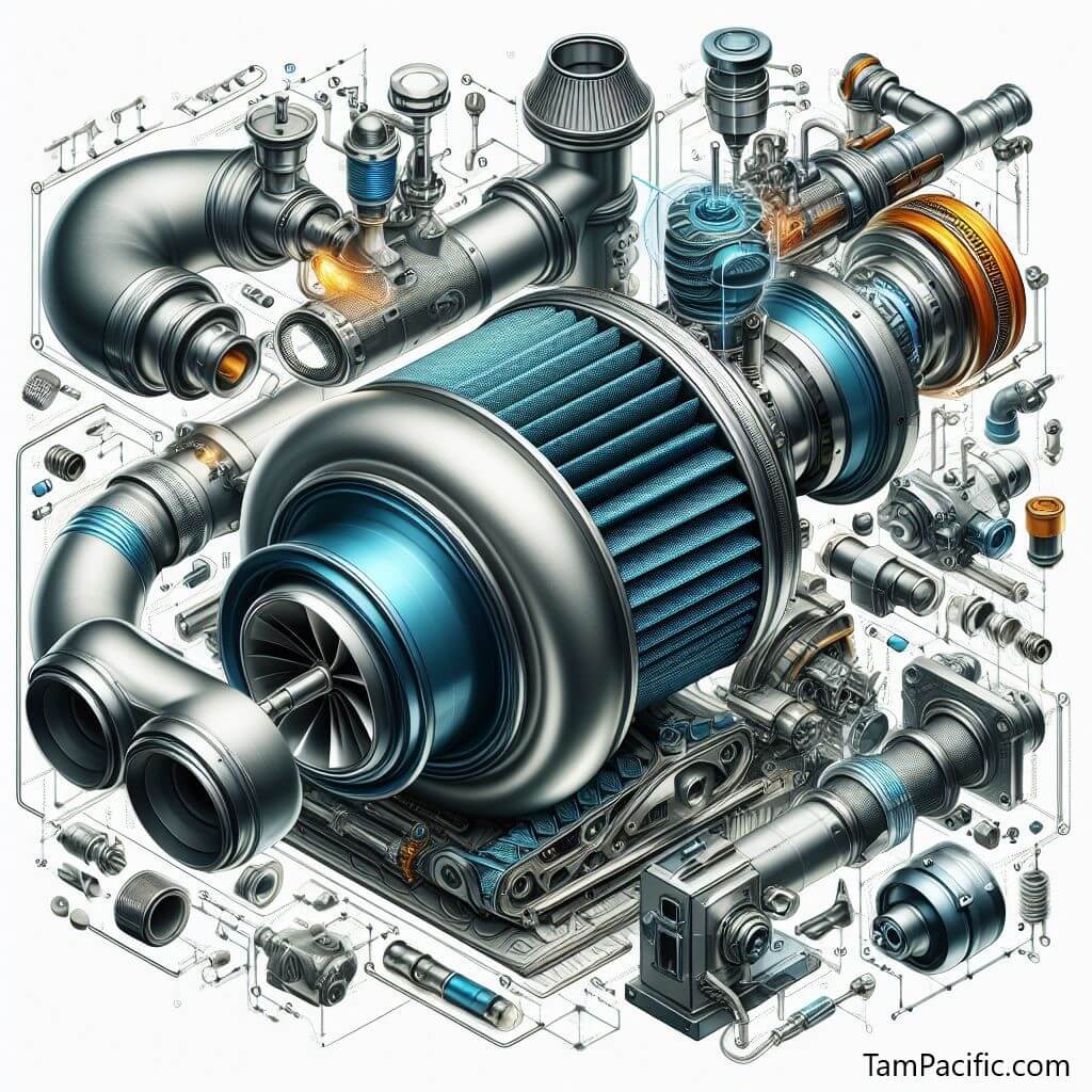
On the other hand, there was no available filter unit for their marine type diesel engine. Some modification by Tulomsaş made it harder to provide suitable solution. As an initial preliminary design concept shown at figure.4, it had been though there had to many guiding fixed plates in order to guide the air which comes to filter horizontally. Main aim was to create a Vortex.
Thus, air will gain enough speed while accessing to turbocharger. When noise reduction criteria comes into the force. It was thought all surfaces must be covered with sound absorptive material. In actual prototype units shown at figure.6, it was seem that application didn’t let us to give enough access area. Narrowing access area will reduce air quantity supplied to the turbocharger. As of above restrictions, number of fixed plates was reduced.
Even design was completed; another restriction came into the force. Customer didn’t expect they will get 75kg in total including sound absorptive materials. There was also no guarantee all these weights could be carried by turbocharger construction itself. Aluminum structure as main frame was decided to lower weigh. There were also a lot of difficulties while manufacturing at least 2 prototype units. Aluminum is not good material for processing. High pressure water jetting was used in order to get smooth corners and surfaces. Another problem was welding procedure during manufacturing. It required pre-heating for avoiding structural deformations.
Distance pieces were designed and manufactured for turbocharger filter housing seating. Units were used just for trials. Inside diameter of casing unit kept as same as original turbocharger suction flange. Distance units fixed with steel wire ropes in order to prevent vibrational movements. At shop trials, one of the filters with silencer unit was fitted with sound absorptive material. Other was left naked with its construction only. Figure.10 show us test installations on PA4-185 diesel engine. Thus It let us to measure difference at both filter units how absorptive material handle sound attenuation. It was observed that there is only limited 3-4dB. When filter unit inside filled with 40mm thickness in total has great influence at pressure drop. It was observed, there should not be more copper filters as secondary filtration for some particulars. It was increased both pressure drop and total weigh. At the same time, manufacturing costs increased partially.
First tests were carried under atmospheric pressure conditions. There was not forced pressure inside test workshop. It seemed that there serious pressure drop even at %25 load as shown at Table12. When maximum allowable pressure drop remembered is 20 milibar, It was a big disappointment for trials. Forced pressure is normally in engine rooms are supplied by mechanical ventilation axial electrical motor fans. It seemed that unless there is no positive pressure inside engine room, turbocharger behaves as vacuum cleaner and tries to suck air. When vacuum conditions are created great pressure drops can exists with structural element.
Here, we had test results as shown on table.12 without positive pressure in test room. These data was taken and recorded as future reference values in order to see how some design changes or modifications result as output values. On above test trials, fore t/c intake filter fitted without filter element inside. Even there is no filtering element inside, two layer of filter casing which shown at figure.7 caused serious pressure drop at aft unit while air was passing through suction channels. At %25 engine loads, 20mmWC permissible pressure drop was exceeded so It required us to cancel two layers of filtering casing. Outer and inner casing faced each other for minimizing air velocity lost while air passing inside. Test trials are being continued. Next phase trials will include positive pressure advantages in engine room.
Table.12: Turbocharger filter with silencer Performance test measurement Results by Argeman.
| Load (%) | 0% | 25% | 50% | 75% | 100% |
|---|---|---|---|---|---|
| Time | 13:30 | 14:10 | 14:30 | – | – |
| Rev. | 600 | 1500 | 1500 | 1500 | 1500 |
| Load (hp) | 0 | 630 | 1200 | – | – |
| Δp room (mmWC) | 0 | 0 | 0 | 0 | – |
| Δp T/C Fore (mmWC) | 10 | 31 | – | – | |
| Δp T/C Aft (mmWC) | 22 | 45 | – | – | – |
| T/C press. Fore (bar) | – | 0.26 | 0.63 | – | – |
| T/C press. Aft (bar) | – | 0.27 | 0.62 | – | – |
3. Results and discussions.
Even all inside surface of turbocharger filter casing is covered with absorptive material; there is no serious sound attenuation. It was observed that there is only limited 3-4dB (decibel).On the other hand, Shop trials didn’t give us expected some sound attenuation changes even at different loads. Sound attenuation amounts were very close at each performance test steps.
Filter unit inside filled with 40mm thickness in total has great influence at pressure drop. It was observed, even amount of copper filters used as secondary filtration was reduced pressure drop through filtration element decreased small amount in conjunction with thickness. Secondary filtration filter element thickness should be kept as minimum as needed. Otherwise, pressure drop increased over limitations.
There are serious impacts on engine performance either at atmospheric pressure condition or at forced pressurized engine room conditions. In order to get easy breath or supply air to any kind of diesel engine, there should be optimum amount of air pressure at where engine is installed.
Conclusion.
According to actual experiment/test and study, the results can be summarized as follows;
From conceptional design to actual performance tests, research and development programmers provide to produce new products and approaches against customer needs. Providing eligibility criteria on turbocharger filter silencer design processes direct research team to look deeply some specific subjects such as sound absorptive material type selection, thickness, filter element type and thickness, complete design, air dynamics, material selection on manufacturing, atmospheric pressure conditions in engine room. All criteria directly affect while getting optimum required prototype product for turbocharger unit.
The future following trends can be clearly identified such as; higher specific power output to archive less weight per kW, higher engine efficiency, lower exhaust emissions, improved engine reliability and longer times between overhauls, lower manufacturing costs.[Heim,K.]
References
[1] Heim,K., (2002). Existing and future demands on the Turbocharging of modern large two-stroke diesel engines. 8th Supercharging conference, 1-2 October 2002, Dresden
[2] EPA,.(1999). Final Regulatory Impact Analysis: Control of Emissions from Marine Diesel Engines, EPA420-R-99-026, November 1999
[3] Hiereth, H., (1986). Testing methods fort he transient behaviour of charged vehicle engines, SAE (Society of automotive Engineers) ref: 860451.
[4] Jenelle, P., (2009). Analysis of a Turbocharger System for a Diesel Engine, Rensselaer Polytechnic Institue, Hartford, Connecticut, December 18, 2009
[5] Born, H., Ch.Roduner, M.Meier,(2004), TPS..-F: A new series of small turbochargers for highest pressure ratios, CIMAC Congress, Kyoto, Paper no.:34.
[6] Codan, E., (2000), Die Aufladung zukünftiger Gross-motoren, 7. Aufladetechnische Konferenz, Dresden, pp.2009-228.
[7] Codan, E., I. Vlaskos, O.Bernand & P. Neuenschwander, (2002) Massnahmen zur Verbesserung des tranienten Betriebs von turboaufgeladenen Grossmotore, 8. Aufladetechnische Konferenz, Dresden.
[8] Semt Pielstick Diesel Engine Descriptive Handbook for PA4-185 type physicalgeography CHAPTER 7: Introduction to the Atmosphere.
[9] International Association of Classification Societies (IACS) rule M28.
[10] ISO 3046-1:2002(E) and ISO 15550:2002(E) ambient reference conditions/requirements. Vikipedia, Lake Van.
Adem Guleryuz
© UCTEA The Chamber of Marine Engineers.
Journal of ETA Maritime Science.
You are viewing the article:
Providing Eligibility Criteria On Turbocharger Filter Silencer Design Processes
Link https://tampacific.com/jems/providing-eligibility-criteria-on-turbocharger-filter-silencer-design-processes.html
Keywords: Diesel Engine; Turbocharger; Air Pressure; Engine Room; Ambient Condition.
Next article: A Qualitative Study on Nutrition of Turkish Seafarers
* This work is licensed under a CC-BY 4.0 International License.